
Joe Hartley – jh@brainiac.com
This document and the files to create this project are available at https://brainiac.com/GearedMazePuzzleBox and my Instructables page.
The project files are available in DXF, SVG, and Lightburn formats and are linked at the bottom of this page.As part of my learning process with my Longer RAY5 10W laser engraver/cutter, I made the Apprentice Maze Puzzle Box from Maker Design Lab. There were a couple of things I found problematic in this design. First was that turning the maze by hand was a bit difficult, in part because part of the inner maze flexed a bit too much in places to give the right leverage to be able to overcome the friction needed. The other maze issue was that people without fingernails found it more difficult to turn the maze.
The pin movement in the maze was another issue – there's not enough friction on the slider plate to get a good grip to move the center pin. I considered gluing a bit of sandpaper on the plate at one point, but I didn't like that idea either.
After another learning project (Display Gears: https://www.instructables.com/Laser-Cut-Display-Gears/), I thought that I could figure out a way to use gears to move things around. A few days later, I had a puzzle box that moves both the maze ring and the pin with thumb-wheels.
This document will detail the construction of the Geared Maze Puzzle Box. I use some of the documentation provided by Maker Design Lab when applicable.
To design the gears, I used Dr. Rainer Hessmer's fine “Online Involute Spur Gear Builder v2” tool. It allowed me to get both the spur and rack and pinion gears just right.
The design and laser control was all handled by the software Lightburn running on Arch Linux systems. It's a great package, but I'm disappointed that Linux support stops at v1.7.
I use a Longer RAY5 10W laser unit with a 400mmx400mm bed. In order to minimize waste, I start with 2'x4' sheets of MDF or plywood, rip them down the middle, and then cross-cut those pieces into 15.75” lengths, giving me six pieces of 12” x 15.75” (400mm x 300mm) board that fits nicely on the laser bed.
The parts are split across into two files, one for the box lid and the second for the bottom. Each file's pieces fit on a 400mm x 300mm board.
Besides the boards, you
will also need a length of ¼” dowel to create axles for the
gears.
Glue the maze (M_AZ) and the gear ring with the small cutout (M_GR) together. Make sure that the cutout on the
ring and on the maze align.
|
|
 |
Glue the four wall parts (2 x L_S1 and 2x L_S2) and the sub-lid (L_SU) together. The sub-lid side with the engravings should
face up and the notches in the bottom of the L_S2
sides should match with the circles cut into the
side of the sub-lid.
 |
 |
 |
Glue the four distance holder parts (L_DI)
vertically to the corners of the lid side walls with the
circular holes (L_S1).

Glue the lid top to
the sub-lid. The holes in the lid top should be
centered in the big circles cut into the sub-lid.
Flip the top if they don't line up. When dry, place the maze assembly in the box lid gear side up and check if it rotates freely (sand the
hole if it doesn’t).

Glue the lid alignment
fixtures (L_AF) into the holes in the lid maze guides (L_MG) with the protrusions on the alignment
fixtures pointing away from the curve on the maze
guides.
 |
 |
Glue the assembled maze guides to the inside of the sub-lid using the engravings for on the sub-lid for placement.
Glue the two maze back guide (M_BG) pieces onto
the maze backplate (M_BP) using the engraving as a
guide. When dry, place the assembly in the maze ring.
 |
 |
Ensure the ¼” dowel spins freely in the lid top
holes; sand the holes if it does not. Cut a ½” length of
dowel. Glue the dowel in a knurled knob (L_KK) so that
it protrudes 1/8” from one side of the knob. On the
other side, glue the 12-tooth gear on to the dowel and
knob, followed by a nut (L_NU). (Note that the nuts are
the 12mm dia. rings, not to be confused with the
spacers, which have a pentagonal shape.) All pieces here
should be fastened together, nothing should spin freely.
When dry, the assembly should be inserted into the
opening in the sub-lid labeled “Maze Gears”. The 1/8” of
dowel should fit into the hole in the lid and the edge
of the knob should fit into the slot between the wall
and the sub-lid. It must spin freely.
 |
 |
 |
Start by ensuring that the 10-tooth gear spins
freely on a piece of ¼” dowel. Glue a 3/8” piece of
dowel in the sub-top hole below the already inserted
gear assembly. When dry, slide the 10-tooth gear
over the dowel , engaging with the 12-tooth gear,
followed by a nut. Glue the nut in place, but make
sure that the 10-tooth gear spins freely when
moved with the thumb-wheel. Be careful not to let
the glue for the nut attach it to the gear!
 |
Create the lock sliders by gluing the lock
slider plates (L_SP) to t he lock
slider connectors (L_CO). Note that there are two
different connectors based on which side of the lid they
go on. See the photo below for proper orientation. Glue
the lock slider add-on squares (L_AS) to the bottom of
the lock slider connectors, fitting them to align with
the corner on the connector as shown below.
 |
 |
 |
 |

|
Glue the maze slider
top (M_ST) to the maze slider bottom (M_SB), using the
etched lines for placement.
 |
 |
The bottom is slightly
narrower than the top – ensure that the racked side of
M_SB and the edge of M_ST are aligned as shown below.

Tap a small brass nail into the marked circle on the
slider top – this is the pin that needs to be guided
through the maze.
Fit the maze assembly in the center of the lid,
aligning with the 1
0-tooth gear and check that it spins freely when turned
with the thumb-wheel.
Place the slider guide (S_GU) over the alignment pieces
(L_AF) and between the guides on the maze back plate.
Make sure the round nub of the center space of the
slider guide is pointed to the pin gear side of the lid
and that the lock slider guide slots are on the opposite
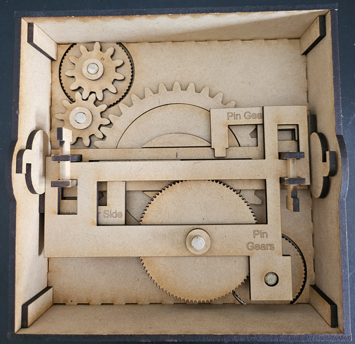
side of the gears. The photo below shows the state of
the assembly so far:
 |
 |
Place the maze slider assembly in the center of the slider guide. Ensure that the pin is in the center of the maze and that the wider end of the slider is on the maze gear side of the lid.
Place the lock sliders
in place, making sure the LS_A pieces fit in the
cut-outs in the slider guide. The bottom of the
slider plates (L_SP) will fit between the slider guide
and the walls. See the photo below. Make sure the lock
sliders are moved all the way outward (in the “locked”
position”) and then glue the circles (L_CI) centrally on
the slider plates (L_SP). (The circles are cut from the
middle of the L_S1 pieces.)
 |
 |
Cut a ¾” piece of dowel. Glue a
knurled knob (L_KK) onto the dowel, leaving 1/8”
protruding from one side. Then glue two spacers
(L_SA) over the shaft and onto the knurled knob.
Next, glue the 29-tooth gear (L_29) on to the
shaft and the spacers. When dry, slide the knob
into the slot in the box lid, fitting the dowel
into the hole in the box lid.
 |
 |

|
 |
 |
 |

|
 |
 |
The only thing left to do
now is to close the box. To do this make sure that the maze pin
is in the middle of the maze and the lock sliders are in the
“unlocked” position (pushed outwards). After putting the lid on
you can move the two lock sliders on the sides to lock the box
and then navigate the pin in the maze all the way outwards. Now
the maze puzzle box is ready to be given away to somebody to
figure out its secret!
Here are the various files used to create the box - choose the
format that works best for you.
